Installing Multiple Amplifiers
There seems to be some confusion when it comes to installing more than one amplifier. Should you use one power wire or multiple wires? Do you ground everything to the same point? How do you split the low level signal? How many items can you connect to your head unit’s remote turn on circuit? Let me share my thoughts on the topic of installing multiple amplifiers.
Power Wire
With more amplifiers you're going to need either more wire or larger wire. If you’ve already installed a power wire for an existing amplifier you may choose to simply install another wire for additional amplifiers. Personally, I prefer to run one new wire that is large enough for all of the amplifiers and any planned upgrades. It’s always better to have a power wire that is larger than you need than a power wire that is too small. The price difference between two wire gauges (i.e. 4 gauge versus 2 gauge) is negligible compared to the cost of having to run a second or larger wire in the future. I would run one wire for several other reasons as well.
First, it's usually cheaper than two wires in terms of material and labor costs. It’s also easier to run one wire as compared to two or more individual wires. You’ll also need to make fewer connections at the battery. Since there is only one wire you only need one ring terminal at the battery post and only one fuse holder for the audio system.
When using one large wire for multiple amplifiers you'll need a way to split the power wire into smaller wires for each component. I prefer to use a regular distribution block, not the fused type. They're less expensive and there's no need for the extra fuses when there is already a fuse holder near the battery that protects the main power wire (you'll have to install this fuse holder). This assumes your amplifiers already have built in fuses that are designed to protect them. For amplifiers that do not have fuse protection you should use a fused distribution block.
Ground Wire
I often ground my components using separate ground points. I could go into all of the scientific reasons for this but it all boils down to noise. In my experience you have less chance for noise when you separate ground points as compared to using a single ground point. That's not to say that either way is a sure fire method to eliminate noise but it helps if they are separated by at least six inches or so I've found.
That being said, any grounding method that is both safe and effective while keeping out noise is a good method. I choose to separate the grounds but some installers choose to run them to the same point. If you choose to run your ground wires to one point you can also use a distribution block. If you do not use a distribution block then you will want to stack your ground wires so that the largest current carrying wire (usually from your largest amplifier) is on the bottom (closest to the ground point) and that your smallest current carrying wire is on the top (closest to the head of your grounding screw).
RCA cables
Now that you have your power and ground wires connected you'll need to give your amplifiers a music signal (usually the RCA cables run from the head unit). The best way would be if your head unit (radio/deck) has a separate set of outputs that can be used on the extra amplifiers. If your head unit is lacking these extra outputs then there are several other options.
If your amplifiers will be powering dissimilar speakers (subs, mids, tweeters, etc.) then you can use an electronic crossover to split and filter the signal going to each amplifier. Sub-bass frequencies would be sent to the subwoofer amplifier and high pass signals would be passed to the other amplifiers. The crossover will have built in line drivers which will increase the voltage of the low level signal. This can help lower the noise of the system.
Some amplifiers will have an RCA pass through circuit which can be used to drive another amplifier in the system. For example, amplifier A would have an RCA output for amplifier B. These are sometimes filtered which has the benefits of an active crossover without the extra equipment or installation expense. If you are using a filtered output make sure that it is adjustable or that it is at least at a useable frequency for your system design.
The least desirable method is the RCA cable Y adapter or splitter. This is a simple way to split a single RCA output into two RCA outputs. It’s basically splicing an RCA signal into two circuits. The drawback is that the signal voltage is also split so that each component is now getting a smaller low level signal which may increase the noise in the system.
Remote Turn On
All amplifiers in the system will need a 12 volt signal that let’s them know when to turn on. Aftermarket head units provide this but it is recommended that you do not connect more than 1-2 components directly to it. This is because a head unit turn on circuit can only supply about 500mA on average. Most electronic components such as amplifiers, active crossovers and equalizers need about 125mA to turn on. As these components age the current draw can be even higher. If this current draw exceeds the rating of the head unit the circuit can burn out completely.
Instead of connecting each component directly you will want to use a relay. The relay will receive the low current signal from the head unit which will trigger the relay. The relay will then connect the 12 volt signal to the amplifiers and other components. Most 12 volt relays can supply up to 30 amps of current which is more than enough for all your turn on circuits. This prevents your head unit from trying to deliver too much current which can burn out the turn on circuitry in the head unit. The generally accepted way to connect a SPDT (single pole, double throw) relay is illustrated below.
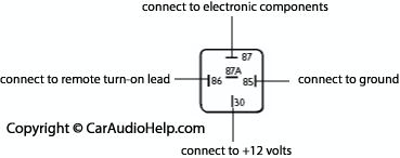
Terminal 85 is connected to ground and terminal 86 is connected to the remote turn on lead from the head unit. These wires could be reversed since they both connect to the relay coil but for this illustration we’ll connect them this way. Terminal 87 of the relay is connected to the electronic components remote turn on terminal. Terminal 30 of the relay is then connected to 12 volts. Again, these wires could be reversed. When the head unit is turned on the remote lead triggers the relay which connects terminals 30 and 87 together, sending a 12 volt signal to all of the electronic components.

The Car Audio Help DVD catalog includes five different videos covering many areas of car audio installation and custom fabrication. Topics range from basic system installation (head units, amplifiers, speakers, etc.) and mobile security (car alarms and remote start) to subwoofer box design and fiberglass fabrication. If you're interested in custom fabrication and car audio installation be sure to check out what we have to offer.
Click here to see the discount DVD packages
Back to the Newsletter Archives Index